.
Kennet
5
30/12/2007
The tool holders consist of three castings - two fairly substantial lumps of iron and the third a flat rectangular casting for the slitting saw holder.
The castings for the lathe tool holder and the milling tool holder are very similar and both require the base of the casting machining flat. This caused much thought as they are a bit of an awkward shape. I ruled out holding them in the 4 jaw chuck and turning the base as it would have been difficult to grip them securely. Fly-cutting was also ruled out, again due to the awkward shape for holding the castings securely. The final option was milling them flat in the mill.
Both the castings have three bosses on the top so I clamped the castings to the milling table after filing the worst lumps off the bases and machined these level first. This gave three level 'feet' on the castings for them to sit on. The castings were then turned over so the newly machined bosses were on the bottom and the base of the castings were machined flat. To machine all the surface meant moving the clamps at some point to another position but this was no problem.
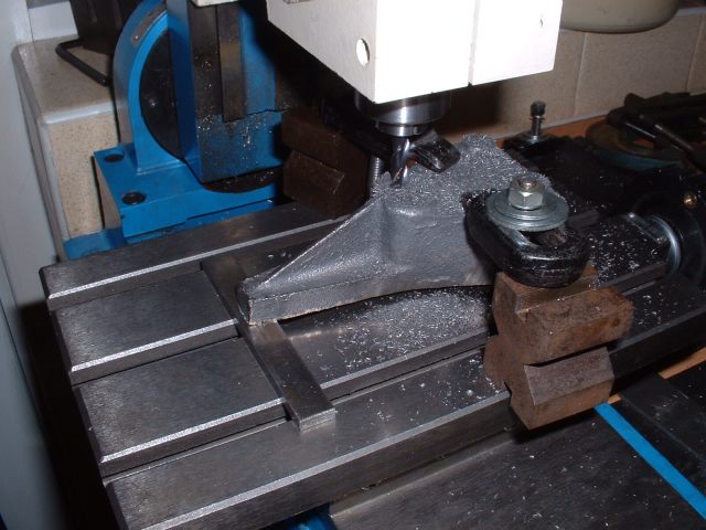
Milling the bosses level

Milling the casting base
Whilst the castings were set up for milling the bases, the narrow end of the castings were recessed to take the brass pointers that read against the scale on the topslide.
A similar proceedure was carried out on the casting for the slitting saw holder which also happens to have three bosses on the underside.
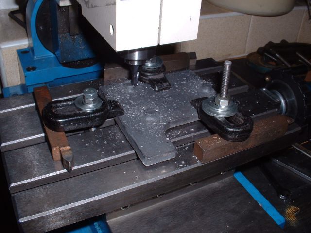
Milling the bosses on the slitting saw holder
The casting for the lathe tool holder has to have a ½" deep slot milled in the end to take the tools. I tried using the mill for this but the set up was not rigid enough and the cutter chattered a lot. I thought of using the vertical slide in the lathe but couldn't get the casting low enough to machine all the slot. In the end I clamped the casting directly to the cross-slide using packing to get the right height. This is a very rigid method but has the disadvantage that you have to alter the packing to cut at different heights. I was using the 1/4" carbide cutter so had to have three passes at the slot. The first cut was taken with the casting the right way up to machine the top edge of the slot. The casting was then turned upside down and the bottom of the slot machined. This left a narrow strip down the middle of the slot to be removed. I actually 'snapped' most of this bit off which left just the bottom bit to be machined off.
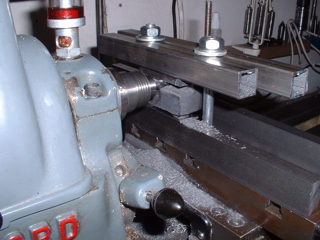
First cut for the slot

Casting turned upside down to take the second cut
The final jobs on this holder were to drill the central boss for the stud that clamps it to the topslide, drill and tap the other two bosses to take the screws that clamp the tools in the holder, and make the pointer from a bit of scrap 18swg brass and screw it in place. The kit didn't have any material for these pointers but I've got plenty of offcuts from making Helen's tanks etc.
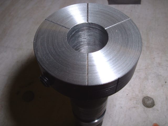
The endmill holder is bored through 3/4" diameter to take the various diameter collets for the endmills to be sharpened and this was done by again clamping the casting onto the cross-slide with packing to bring it to the right height. I forgot to take a photo of this so you'll have to use your imagination! The casting was then drilled for the fixing stud and the collet clamping screw and the pointer made as before.
The collets are simple turning jobs from steel bar and I made three different sizes - 1/4", 3/8", and 1/2" bore. The drawings suggest a 5/8" bore as well but I don't have any mills that big so I did not bother. I can always make one later if necessary.
The collets need index marks engraving on them to align the milling cutters when they are held in the collets. A line is engraved across the face of the collet to line up the cutting edges of the mill and four lines at 90° engraved on the edge of the collet to line up with a mark on the holder. These four lines are used to align the collet for grinding the four cutting edges of the endmills.
A simple way to do this is to put the collet in the four jaw chuck and scribe the lines with a lathe tool held in the toolpost with the point set to centre height. The indexing of the lines is done by putting a suitable length of bar between the lathe bed and each chuck jaw in turn. That gives you the four equally spaced lines around the edge of the collet. At one of the chuck positions the line across the face of the collet is scribed.
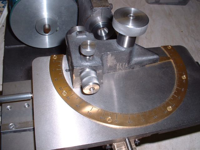
Engraving the index marks on the collets using the chuck jaws for dividing
At this point it occurred to me that there are now a lot of milling cutters about with three cutting edges. Whilst the marks just engraved are suitable for two and four edge cutters they would not be much use for three edge ones. So I decided to engrave a second set of lines on the collets which would enable the newer cutters to be sharpened as well. This simply entailed mounting the collets in the three jaw chuck and scribing two more lines at 120° to the original ones using the bar between the chuck jaws and the lathe bed again. The collet is held in the chuck so that when the bar is under the first jaw the scribing tool lines up with the previously engraved lines. The only thing to watch is that the new index marks on the edge of the collet have to be at 90° to the new lines on the face and not in line! After the lines on the face are engraved the collet needs to be rotated by 90° in the chuck before the edge marks are done. This can be easily done as the existing edge marks are engraved at 90° intervals.
Index marks for 2, 3, and 4 edge cutters
Final job on the collets was to drill and tap the larger diameter to take a 2BA grub screw to clamp the milling cutters in place.
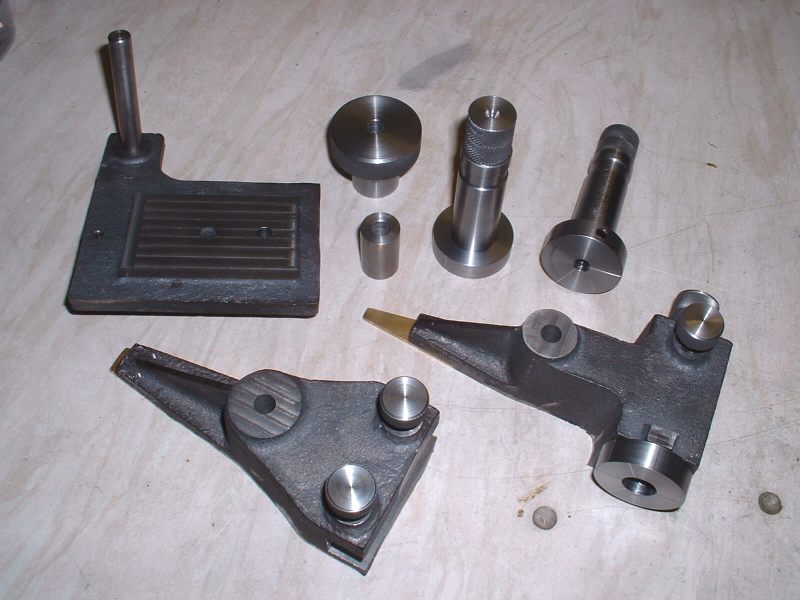
Lathe tool and endmill holders with partly finished slitting saw holder
Endmill holder in position - just need a grinding wheel!
06/01/2008
Another year passed by! They seem to go quicker every time!
It was time to tackle the arbors that each grinding wheel fits on and as I have 6 wheels this meant making 6 arbors! They are all virtually the same except for the outer diameter of the flange and the length of the centre stub that fits into the wheel.
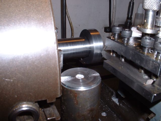
The first job was to set the topslide over to 30° to match the taper in the end of the main spindle. This was then checked by first turning a taper on the end of the bar and checking the fit in the spindle taper using marking blue. A slight adjustment to the angle was called for to get an even seat all over the taper. The topslide was then left at this setting during all the following machining and the parallel sections turned using the leadscrew to move the saddle.
When I was happy with the fit of the taper the end of the bar was turned down to form the 5/16" diameter parallel section which was made a nice snug fit in the bore of the spindle. The next section of the bar was turned down to 3/4" diameter to begin with and then turned to form the 30° taper using the topslide.

Turning the 30° taper
The end of the parallel section was then drilled and tapped 2BA to take the drawbar that holds the arbors into the spindle and then the embryo arbor was parted off leaving enough metal to machine the grinding wheel side. This proceedure was carried out for all six arbors before going any further - a bit of mass production!
Each arbor was then held by the parallel bit in a collet and the other side of the flange machined to size. Finally, the boss was drilled and tapped 1/4" BSF to take the bolt that secures the wheel.

Turning the other side of the flange
Each arbor now required a thick recessed washer to clamp the grinding wheel and these were simple turning and parting off jobs from steel bar. I must admit that I was getting a bit bored towards the end of this particular job as all the work was a bit repetitious!

Four wheels on their arbors and one arbor yet to be fitted

Almost ready to go!
The kit only contained four securing screws for the arbors so I'll have to find a couple more suitable ones from somewhere.
That just leaves the detent to make for the slitting saw holder and that's about it. At this point I decided to give all the castings a coat of paint as if I don't do it now I probably never will! When the paint dries I'll put up a few photos of the finished item.
<Previous Page........Next Page>